Features
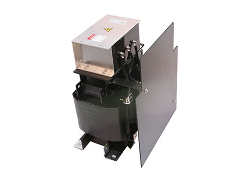
The sine wave filter transforms the PWM Output signal of the electro motor into a smooth sine wave of the low residual ripple voltage so as to prevent the damaged to the winding insulation of the motor. It also reduces the occurrence of the distributed capacitance cause by the over-length of cable and the phenomenon of resonances which is resulted from distributed inductance . Besides .It eliminates the over-voltage of the motor caused by high dv/dt, spares the damage of the motor in advance resulted from the eddy-current loss .the sine wave filter also reduces the perceivable noise of the electro motor.
This sine wave filter adopts the foil winding structure and the copper bar leading-out .It is featured with DC resistance . Strong resistance to electromagnetism and excellent overload ability in short time .The usage of F or above grade composite insulating materials with high performance allows for the reliable performance of the equipment under harsh working conditions .Its strong insulating strength makes it possible to bear ultra high voltage shock . The vacuum pressure impregnation process adopted in this sine wave filter reduces the perceivable noise to a low degree.
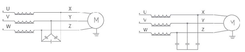
Electrical Schematic Diagrams
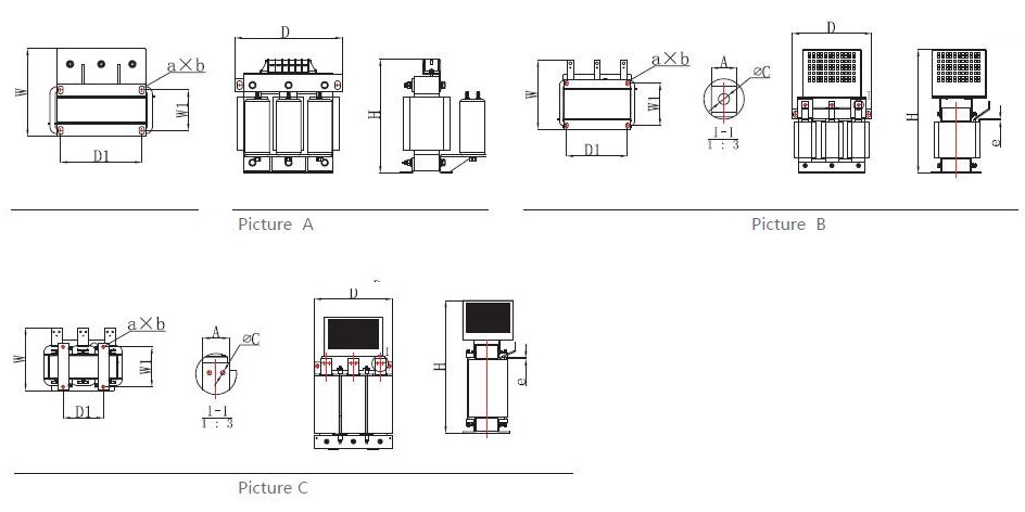
Outline & Mounting Dimension(Unit:mm)
Output 380V Sine Filter Selection Model
| Type | Power (kW) | Rated Current (A) | Picture | Dimension (±0.5mm) | Gross weight (kg) | ||||
| D*H*W(mm) | D1*W1 (mm) |
a*b (mm) |
∮c c(mm) |
A*e (mm) |
|||||
| OSF-0015-EISA-E4M0 | 5.5 | 15A | A | 250*270*200 | 182*91 | 11*18 | / | / | 18 |
| OSF-0020-EISA-E3M0 | 7.5 | 20A | 250*280*220 | 182*100 | 11*18 | / | / | 22 | |
| OSF-0030-EISA-E2M0 | 11 | 30A | 250*270*230 | 182*106 | 11*18 | / | / | 22 | |
| OSF-0040-EISA-E1M4 | 15 | 40A | 250*280*240 | 182*121 | 11*18 | / | / | 26 | |
| OSF-0050-EISA-E1M2 | 18.5 | 50A | 290*290*230 | 214*110 | 11*18 | / | / | 26 | |
| OSF-0060-EISA-E1M0 | 22 | 60A | 290*290*300 | 214*120 | 11*18 | / | / | 31 | |
| OSF-0080-EISA-EM80 | 30 | 80A | 320*320*320 | 243*142 | 12*20 | / | / | 45 | |
| OSF-0090-EISA-EM65 | 37 | 90A | B | 320*500*270 | 243*159 | 12*20 | Φ11 | 25*5 | 59 |
| OSF-0120-EISA-EM52 | 45 | 120A | 320*510*300 | 243*169 | 12*20 | Φ11 | 25*5 | 62 | |
| OSF-0150-EISA-EM45 | 55 | 150A | 395*590*295 | 225*175 | 15*25 | Φ11 | 25*5 | 77 | |
| OSF-0200-EISA-EM35 | 75 | 200A | 400*620*320 | 225*200 | 15*25 | Φ11 | 30*5 | 94 | |
| OSF-0250-EISA-EM30 | 110 | 250A | 400*680*345 | 225*225 | 15*25 | Φ11 | 30*5 | 110 | |
| OSF-0300-EISA-EM24 | 132 | 300A | 405*720*360 | 225*225 | 15*25 | Φ11 | 30*6 | 121 | |
| OSF-0360-EISA-EM20 | 160 | 360A | 430*720*390 | 245*250 | 15*25 | Φ13 | 40*5 | 158 | |
| OSF-0450-EISA-EM15 | 200 | 450A | 430*720*400 | 250*250 | 15*25 | Φ14 | 40*5 | 169 | |
| OSF-0500-EISA-EM15 | 250 | 500A | 460*800*390 | 270*250 | 15*25 | Φ14 | 50*5 | 197 | |
| OSF-0600-EISA-EM12 | 280 | 600A | 480*860*400 | 275*250 | 15*25 | Φ14 | 50*5 | 243 | |
| OSF-0660-EISA-EM10 | 315 | 660A | 470*780*440 | 300*250 | 15*25 | Φ14 | 50*5 | 257 | |
| OSF-0750-EISA-EM09 | 355 | 750A | 550*900*440 | 275*300 | 15*25 | Φ14 | 50*10 | 284 | |
| OSF-0900-EISA-E75U | 400 | 900A | C | 550*940*470 | 275*300 | 15*25 | Φ13 | 60*10 | 317 |
| OSF-1000-EISA-E60U | 450 | 1000A | 550*945*470 | 275*300 | 15*25 | Φ13 | 60*10 | 274 | |
| OSF-1200-EISA-E65U | 500 | 1200A | 600*1010*490 | 300*300 | 15*25 | Φ13 | 80*8 | 412 | |
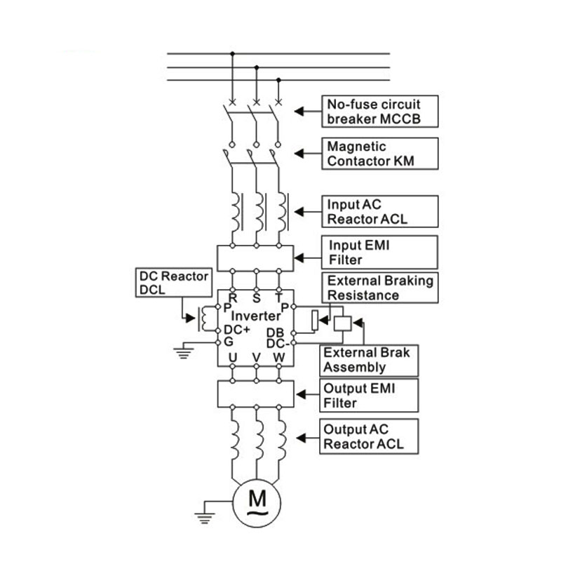
Wiring Diagram for Inverter System
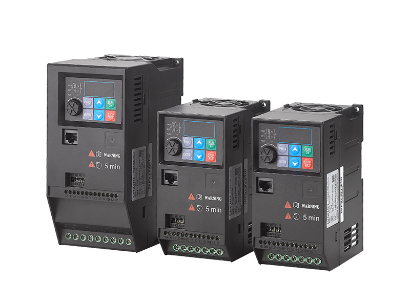
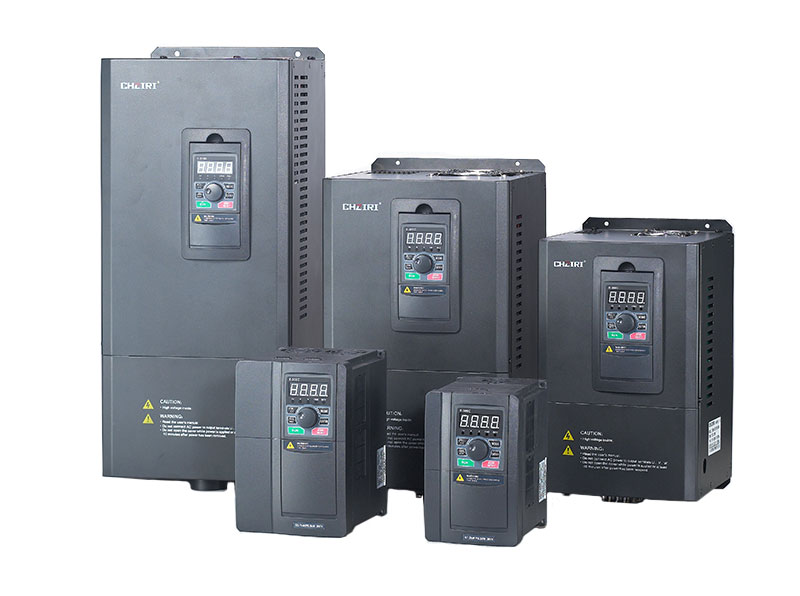
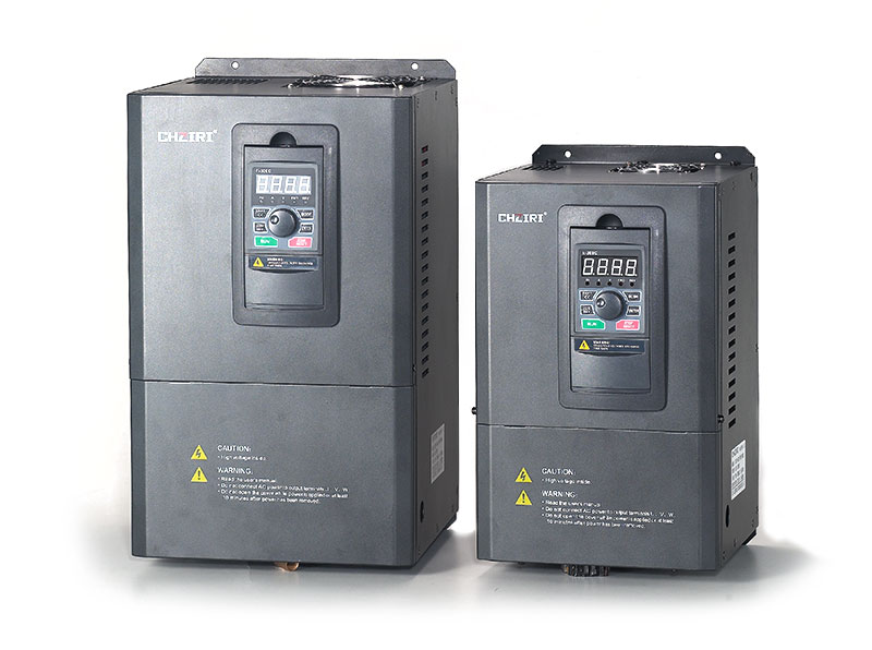
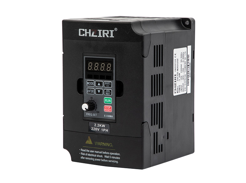
Related Products
News Center
> Double Motor Life: Adding a ZJR7 Soft Starter to DOL Start | ZIRI
If you manage industrial motors, you have probably noticed that motors started with direct‑on‑line (DOL) methods tend to fail earlier than expected—winding insulatio...
> How to Choose a Solar Pumping Inverter for Agriculture | ZIRI
For many farmers, the cost of diesel or grid electricity for irrigation has become a growing financial burden, especially in regions where power supply is inconsiste...
> Stop VFD Overheating with Proper Carrier Frequency Setting
Every maintenance engineer knows the frustration: an alarm light flashing on a drive, followed by a costly production pause. The culprit is often heat—specifically, ...
> Why Your VFD Trips Overcurrent – 3 Quick Fixes
Another production stoppage. Another fault code blinking on the drive display. You reset it, restart the line, and minutes later—the same trip. You are not alone.
