Product introduction
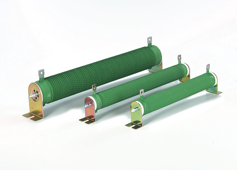
The wirewound resistor is made by fixing two leading-out terminals on the cylindrical ceramic tube which is coiled by bandlet and wave shape alloy resistance wire. The surface of the ceramic tube is coated by layer of coating which is resistant to flaming and high temperature. As the framework of the resistance wire. The ceramic tube can also work as the radiator .this product can be made to order .It is suitable for simulated load test .the discharging of equipment .automatic control and the dynamic braking of the transducer.
Two terminal extensions are fixed on both ends of a ceramic tube on whose surface winds wave-shaped alloy resistance wire and a high temperature-resistant and fireproof coating are applied. The ceramic tube can function as resistance wire skeleton and heat radiator as well . This product can be customized to special needs of customers and applicable to simulation load test, equipped discharge, automated control and inverter’s energy loss brake.
Technical Data:
Rated Power Range: 50W-2500W
Voltage Range: 0.5KV—10KV
Resistance Range: 1R-1KR
Dielectric Voltage: AC2.5KV-20KV/1min 50Hz
IP Class: IP00
Vibration: 1g
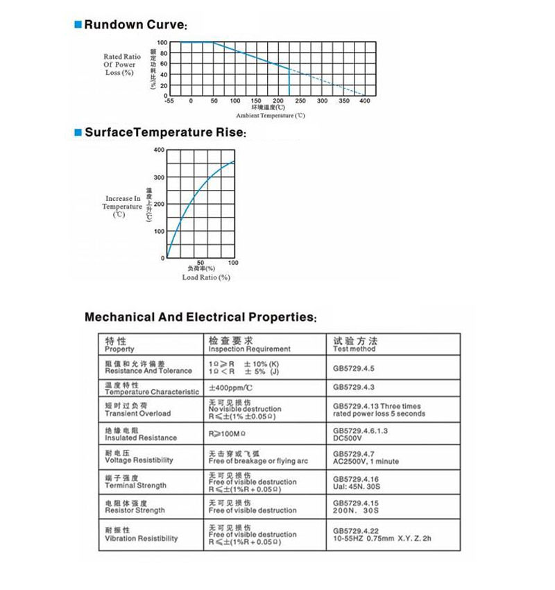
Rated Temperature Rise: 375℃
Temperature Coefficient: 80-400ppm/℃
Carrier Material: 0Cr25AL5/Ni80Cr20 Optional
Advantage: Work in high voltage
Disadvantage: Inferior vibration
Packing: Paper box
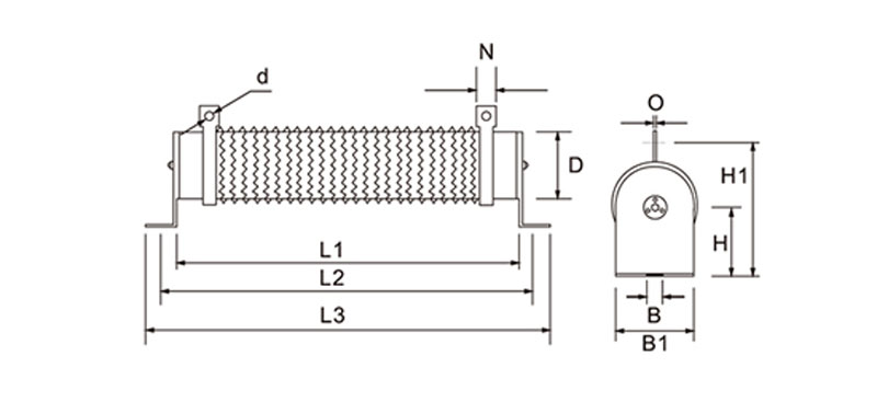
Outline& Mounting Dimension (Unit:mm)
|
Rated power (w) |
Dimension(mm) |
||||||||||
|
L1(±2) |
L2(±5) |
L3(±3) |
D(±2) |
B |
B1 |
H |
H1(±3) |
N |
¢d |
O |
|
|
50 |
102 |
124 |
146 |
28 |
6.5 |
28 |
28 |
61 |
10 |
4.5 |
1.2 |
|
60 |
102 |
124 |
146 |
28 |
6.5 |
28 |
28 |
61 |
10 |
4.5 |
1.2 |
|
80 |
152 |
174 |
196 |
28 |
6.5 |
28 |
28 |
61 |
10 |
4.5 |
1.2 |
|
100 |
182 |
204 |
226 |
28 |
6.5 |
28 |
28 |
61 |
10 |
4.5 |
1.2 |
|
120 |
182 |
204 |
226 |
28 |
6.5 |
28 |
28 |
61 |
10 |
4.5 |
1.2 |
|
150 |
195 |
217 |
239 |
40 |
8 |
40 |
41 |
81 |
12 |
5.5 |
2.0 |
|
200 |
195 |
217 |
239 |
40 |
8 |
40 |
41 |
81 |
12 |
5.5 |
2.0 |
|
300 |
282 |
304 |
326 |
40 |
8 |
40 |
41 |
81 |
12 |
5.5 |
2.0 |
|
400 |
282 |
304 |
326 |
40 |
8 |
40 |
41 |
81 |
12 |
5.5 |
2.0 |
|
500 |
316 |
338 |
360 |
50 |
8 |
50 |
45 |
101 |
16 |
6 |
2.0 |
|
600 |
345 |
367 |
389 |
40 |
8 |
40 |
41 |
81 |
12 |
5.5 |
2.0 |
|
750 |
316 |
338 |
360 |
50 |
8 |
50 |
45 |
101 |
16 |
6 |
2.0 |
|
1000 |
300 |
325 |
350 |
60 |
8.5 |
60 |
60 |
119 |
16 |
6 |
2.0 |
|
1200 |
415 |
440 |
465 |
60 |
8.5 |
60 |
60 |
119 |
16 |
6 |
2.0 |
|
1500 |
415 |
440 |
465 |
60 |
8.5 |
60 |
60 |
119 |
16 |
6 |
2.0 |
|
2000 |
510 |
535 |
560 |
60 |
8.5 |
60 |
60 |
119 |
16 |
6 |
2.0 |
|
2500 |
600 |
625 |
650 |
60 |
8.5 |
60 |
60 |
119 |
16 |
6 |
2.0 |
Note:For bigger power inverter ,we suggest you use braking resistor box.
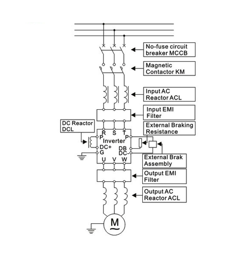
Wiring Diagram for Inverter System
Recommended brake assembly matching specification
| Inverter | Braking Unit | Braking resistor | ||||
| Voltage(V) | Motor(KW) | Model | Quantity(PCS) | Recommed resistor value | Resisitor specification | Quantity(PCS) |
| 220V | 0.75KW | Built-in | 80W200Ω | 80W200Ω | 1 | |
| 1.5KW | Built-in | 200W100Ω | 200W100Ω | 1 | ||
| 2.2KW | Built-in | 300W70Ω | 300W70Ω | 1 | ||
| 3.7KW | Built-in | 400W40Ω | 400W40Ω | 1 | ||
| 380V | 0.75KW | Built-in | 80W750Ω | 80W750Ω | 1 | |
| 1.5KW | Built-in | 200W400Ω | 200W400Ω | 1 | ||
| 2.2KW | Built-in | 300W250Ω | 300W250Ω | 1 | ||
| 3.7KW | Built-in | 400W150Ω | 400W150Ω | 1 | ||
| 5.5KW | Built-in | 600W100Ω | 600W100Ω | 1 | ||
| 7.5KW | Built-in | 800W75Ω | 800W75Ω | 1 | ||
| 11KW | Built-in | 1000W50Ω | 1000W50Ω | 1 | ||
| 15KW | Built-in | 1500W40Ω | 1500W40Ω | 1 | ||
| 18.5KW | 4030 | 1 | 2500W35Ω | 2500W35Ω | 1 | |
| 22KW | 4030 | 1 | 3000W27.2Ω | 3000W27.2Ω | 1 | |
| 30KW | 4030 | 1 | 5000W19.2Ω | 2500W38.4Ω | 2 | |
| 37KW | 4045 | 1 | 6000W16Ω | 2000W48Ω | 3 | |
| 45KW | 4045 | 2 | 9600W13.6Ω | 2500W54.4Ω | 4 | |
| 55KW | 4030 | 2 | 12000W10Ω | 2000W60Ω | 6 | |
| 75KW | 4045 | 2 | 19200W6.8Ω | 2500W54.4Ω | 8 | |
| Braking Resistor Box | Quantity(PCS) | |||||
| 90KW | 4030 | 3 | 9600W20Ω | 3 | ||
| 100KW | 4220 | 1 | 9600W20Ω | 3 | ||
| 132-160KW | 4220 | 1 | 40KW3.4Ω | 1 | ||
| 185-220KW | 4220 | 1 | 60KW3.2Ω | 1 | ||
| 250-315KW | 4220 | 2 | 40KW4.5Ω | 2 | ||
| 315-600KW | 4220 | 3 | 60KW3Ω | 3 | ||
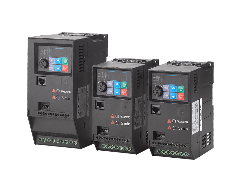
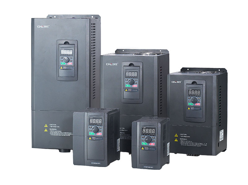
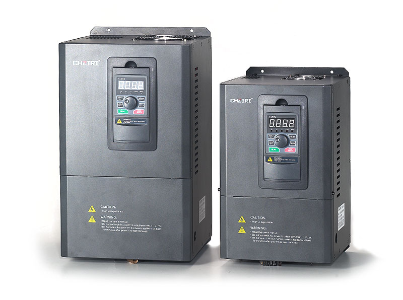
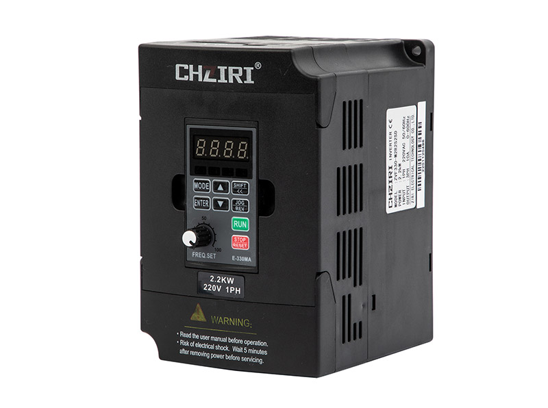
Related Products
News Center
> 3 Daily Checks for Your ZJR7 Soft Starter | Contacts & Cooling Maintenance | ZIRI
You walk past the motor control panel every morning. The ZJR7 soft starter is running—no alarms, no trips, no obvious problems. But the failures that cost the most d...
> How Does an Intelligent Pump Controller Automatically Adjust Pump Speed and Pressure?
Ever wonder how an intelligent pump controller maintains constant pressure without manual adjustment? From pressure sensors and PID control loops to VFD-driven speed...
> Step-by-Step: Setting Parameters on ZJR7-B Soft Starter | ZIRI
You have just installed a new ZJR7-B soft starter, wired the motor, and powered it up. The LCD display lights up, but now you are staring at a menu of parameters—sta...
> ROI Analysis: Upgrading to a Constant Pressure Pump Controller | ZIRI
If you manage a water pumping system—whether for a residential building, a commercial facility, or an industrial process—you have likely noticed the telltale signs o...
